Sunday 28 June 2015

My Probe


Block Diagram
ARDUINO
Arduino is an open-source computer hardware and software company, project and user community that designs and manufactures kits for building digital devices and interactive objects that can sense and control the physical world.
Arduino started in 2005 as a project for students at the Interaction Design Institute Ivrea in Ivrea, Italy. At that time program students used a "BASIC Stamp" at a cost of $100, considered expensive for students. Massimo Banzi, one of the founders, taught at Ivrea. The name "Arduino" comes from a bar in Ivrea, where some of the founders of the project used to meet.
This project uses Arduino MEGA 2560 development board.

The Arduino Mega 2560 is a microcontroller board based on the ATmega2560. It has 54 digital input/output pins (of which 15 can be used as PWM outputs), 16 analog inputs, 4 UARTs (hardware serial ports), a 16 MHz crystal oscillator, a USB connection, a power jack, an ICSP header, and a reset button. It contains everything needed to support the microcontroller; simply connect it to a computer with a USB cable or power it with a AC-to-DC adapter or battery to get started.

SPECIFICATIONS AND PIN CONFIGURATION
Microcontroller
ATmega2560
Operating Voltage
5V
Input Voltage (recommended)
7-12V
Input Voltage (limits)
6-20V
Digital I/O Pins
54 (of which 15 provide PWM output)
Analog Input Pins
16
DC Current per I/O Pin
40 mA
DC Current for 3.3V Pin
50 mA
Flash Memory
256 KB of which 8 KB used by bootloader
SRAM
8 KB
EEPROM
4 KB
Clock Speed
16 MHz
The board can operate on an external supply of 6 to 20 volts. If supplied with less than 7V, however, the 5V pin may supply less than five volts and the board may be unstable. If using more than 12V, the voltage regulator may overheat and damage the board. The recommended range is 7 to 12 volts.
The power pins are as follows:
  • VIN. The input voltage to the Arduino board when it's using an external power source (as opposed to 5 volts from the USB connection or other regulated power source). You can supply voltage through this pin, or, if supplying voltage via the power jack, access it through this pin.
  • 5V. This pin outputs a regulated 5V from the regulator on the board. The board can be supplied with power either from the DC power jack (7 - 12V), the USB connector (5V), or the VIN pin of the board (7-12V). Supplying voltage via the 5V or 3.3V pins bypasses the regulator, and can damage your board. We don't advise it.
  • 3V3. A 3.3 volt supply generated by the on-board regulator. Maximum current draw is 50 mA.
  • GND. Ground pins.
  • IOREF. This pin on the Arduino board provides the voltage reference with which the microcontroller operates. A properly configured shield can read the IOREF pin voltage and select the appropriate power source or enable voltage translators on the outputs for working with the 5V or 3.3V.
Each of the 54 digital pins on the Mega can be used as an input or output, using pinMode(), digitalWrite(), and digitalRead() functions. They operate at 5 volts. Each pin can provide or receive a maximum of 40 mA and has an internal pull-up resistor (disconnected by default) of 20-50 kOhms. In addition, some pins have specialized functions:
  • Serial: 0 (RX) and 1 (TX); Serial 1: 19 (RX) and 18 (TX); Serial 2: 17 (RX) and 16 (TX); Serial 3: 15 (RX) and 14 (TX). Used to receive (RX) and transmit (TX) TTL serial data. Pins 0 and 1 are also connected to the corresponding pins of the ATmega16U2 USB-to-TTL Serial chip.
  • External Interrupts: 2 (interrupt 0), 3 (interrupt 1), 18 (interrupt 5), 19 (interrupt 4), 20 (interrupt 3), and 21 (interrupt 2). These pins can be configured to trigger an interrupt on a low value, a rising or falling edge, or a change in value. See the attachInterrupt()function for details.
  • PWM: 2 to 13 and 44 to 46. Provide 8-bit PWM output with the analogWrite() function.
  • SPI: 50 (MISO), 51 (MOSI), 52 (SCK), 53 (SS). These pins support SPI communication using the SPI library. The SPI pins are also broken out on the ICSP header, which is physically compatible with the Uno, Duemilanove and Diecimila.
  • LED: 13. There is a built-in LED connected to digital pin 13. When the pin is HIGH value, the LED is on, when the pin is LOW, it's off.
  • TWI: 20 (SDA) and 21 (SCL). Support TWI communication using the Wire library. Note that these pins are not in the same location as the TWI pins on the Duemilanove or Diecimila.
The Mega2560 has 16 analog inputs, each of which provide 10 bits of resolution (i.e. 1024 different values). By default they measure from ground to 5 volts, though is it possible to change the upper end of their range using the AREF pin and analogReference() function.
There are a couple of other pins on the board:
  • AREF. Reference voltage for the analog inputs. Used with analogReference().
  • Reset. Bring this line LOW to reset the microcontroller. Typically used to add a reset button to shields which block the one on the board.

Programming

The Arduino Mega can be programmed with the Arduino software.
The ATmega2560 on the Arduino Mega comes preburned with a bootloader that allows you to upload new code to it without the use of an external hardware programmer. It communicates using the original STK500 protocol.
The Arduino integrated development environment (IDE) is a cross-platform application written in Java, and derives from the IDE for the Processing programming language and the Wiring projects. It is designed to introduce programming to artists and other newcomers unfamiliar with software development. It includes a code editor with features such as syntax highlighting, brace matching, and automatic indentation, and is also capable of compiling and uploading programs to the board with a single click. A program or code written for Arduino is called a sketch.
Arduino programs are written in C or C++. The Arduino IDE comes with a software library called "Wiring" from the original Wiring project, which makes many common input/output operations much easier. Users only need define two functions to make a runnable cyclic executive program:
  • setup(): a function run once at the start of a program that can initialize settings
  • loop(): a function called repeatedly until the board powers off.
          SENSORS :
          SOIL MOISTURE SENSOR :
Soil moisture sensors measure the water content in soil. A soil moisture probe is made up of multiple soil moisture sensors. Since analytical measurement of free soil moisture requires removing a sample and drying it to extract moisture, soil moisture sensors measure some other property, such as electrical resistance, dielectric constant, or interaction with neutrons, as a proxy for moisture content. The relation between the measured property and soil moisture must be calibrated and may vary depending on soil type.

Specifications

  • Range: 0 to 45% volumetric water content in soil (capable of 0 to 100% VWC with alternate calibration)
  • Accuracy: ±4% typical
  • Resolution: 0.1%
  • Power: 3 mA @ 5VDC
  • Operating temperature: –40°C to +60°C
  • Dimensions: 8.9 cm × 1.8 cm × 0.7 cm (active sensor length 5 cm) 
TEMPERATURE AND HUMIDITY SENSOR :
The DHT11 is a basic, ultra low-cost digital temperature and humidity sensor. It uses a capacitive humidity sensor and a thermistor to measure the surrounding air, and spits out a digital signal on the data pin. Its fairly simple to use, but requires careful timing to grab data. The only real downside of this sensor is you can only get new data from it once every 2 seconds, so when using library, sensor readings can be up to 2 seconds old.
SPECIFICATIONS
  • Low cost
  • 3 to 5V power and I/O
  • 2.5mA max current use during conversion (while requesting data)
  • Good for 20-80% humidity readings with 5% accuracy
  • Good for 0-50°C temperature readings ±2°C accuracy
  • No more than 1 Hz sampling rate (once every second)
  • Body size 15.5mm x 12mm x 5.5mm
  • 4 pins with 0.1" spacing
 INFRARED SENSOR :

The IR Sensor-Single is a general purpose proximity sensor. Usually it is used for collision detection or obstacle detection. The module consist of an IR emitter and IR receiver pair. The high precision IR receiver always detects IR signal. The module consists of 358 comparator IC. The output of sensor is high whenever the IR receiver receives a signal of IR frequency and low otherwise. The on-board LED indicator helps user to check status of the sensor without using any additional hardware. The power consumption of this module is low. It gives a digital output.

Features

  • General Purpose Proximity Sensor.
  • IR emitter and IR receiver pair.
  • LED indicator for sensor output.
  • Very compact.
  • Low power consumption.
  • LM358 for Digital Output.

GAS SENSOR :

MQ 2 Gas sensor
The Grove - Gas Sensor(MQ2) module is useful for gas leakage detecting. It can detect LPG, i-butane, methane, alcohol, Hydrogen, smoke and so on. 
MQ 6 Gas Sensor
Sensitive material of MQ-6 gas sensor is SnO2, which with lower conductivity in clean air. When the target flammable gas exist, the sensor’s conductivity gets higher along with the gas concentration rising. MQ-6 gas sensor can detect kinds of flammable gases, especially has high sensitivity to LPG (propane). It is a kind of low-cost sensor for many applications.
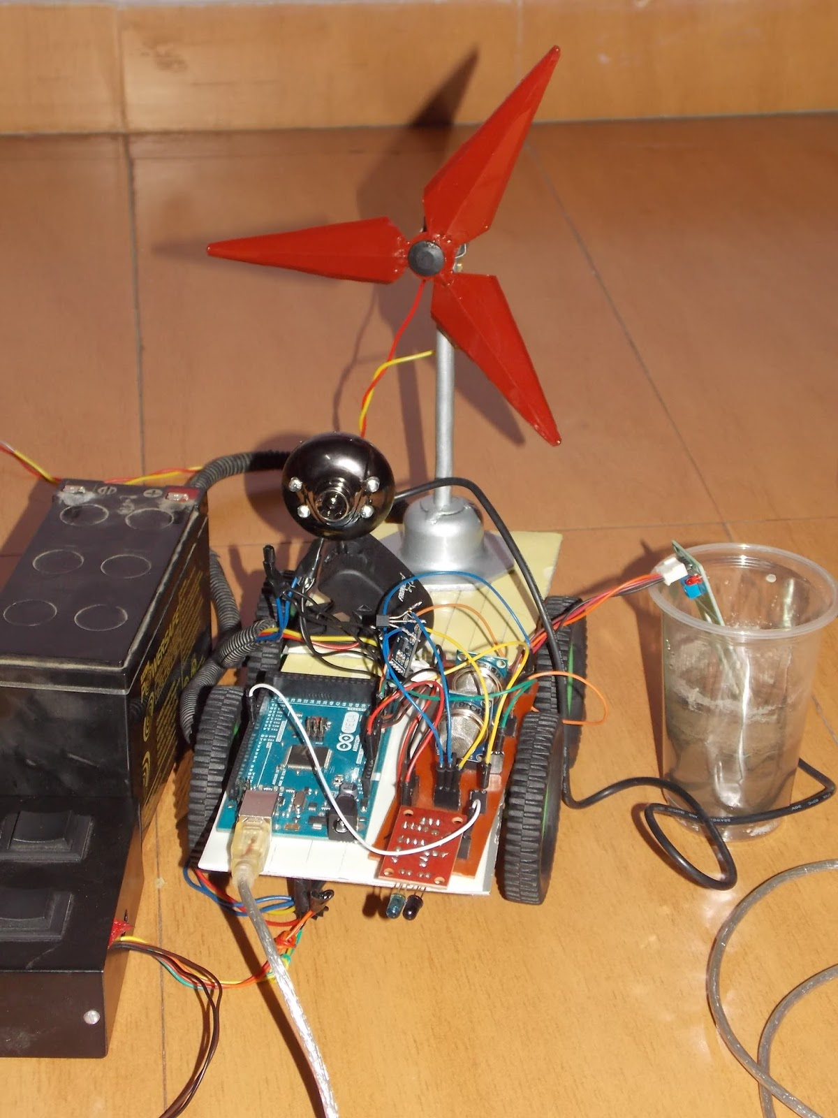
  WINDMILL :


A wind turbine is a device that converts kinetic energy from the wind into electrical power. The speed of wind on planets like Mars and Jovian gas giant planets (Jupiter, Saturn, Uranus, and Neptune) is high enough to produce energy needed by the rover.
The speed of wind on Mars ranges from 10 mps to 30 mps or 20 miles/h to 60 miles/h. Currently, the windmill employed on Earth produces 70% of energy at 12 mph and the power produced by a windmill is 250 W to 1.8 MW. On Jovian planets like Neptune the speed of wind is 1,100 kph to 2,100 kph. The rover needs 140 W of energy to operate. So, windmill employed on rover can complete its power requirements.
To prevent damage, the windmill stops functioning when the speed of the wind exceeds 25 mph. Rover can be installed with small windmill which can generate energy. As, the speed of the wind is more than 25 mph, so, the wings of the windmill must be strong enough to tolerate the pressure of the high speed wind. So, small changes made in the windmill can be helpful in installing it on rovers and can act as a good alternate source of energy for rovers.
RESULT ANALYSIS AND DISCUSSION
This project deals with the analysis of results of various sensors. Results of sensors like Temperature, air, Soil moisture etc. are studied and examined. With the means of graph  the change in values of these sensors can be studied very accurately. This project helps to deal with the understanding of those places where it is difficult to analyse the physical and environmental conditions.
Use of Arduino to program sensors and the display of graphs have helped a lot in better understanding of project. Until now the design of this rover is not completely perfect, to make the rover more useful a lot of changes needed to be done in future so that it can display a wide variety of data and may help to understand the physical and environmental  conditions more  clearly and accurately.
CONCLUSION :
This model is designed keeping in view the shortcomings of the models sent in space. The changes are needed to be made in power supply, balancing and employment of sensors to search for extraterrestrial life form.
A robotic spacecraft is a spacecraft with no humans on board, usually under telerobotic control. A robotic spacecraft designed to make scientific research measurements is often called a space probe. Many space missions are more suited to telerobotic rather than crewed operation, due to lower cost and lower risk factors. In addition, some planetary destinations such as Venus or the vicinity of Jupiter are too hostile for human survival, given current technology. Outer planets such as Saturn, Uranus, and Neptune are too distant to reach with current crewed spaceflight technology, so telerobotic probes are the only way to explore them.
The increasing use of automation in future space systems is a fundamental component of future space exploration which will resemble remotely distributed, net-worked operations. As such, the design of both manned and unmanned future space systems has significant HSC (Human Supervisory Control) implications. However, only a handful of projects have recognized the importance of HSC for future space systems. In addition to those described previously, Cummings described a preliminary design for the systems status display of a future lunar landing vehicle which would have considerably reduced reliance on Mission Control without compromising the probability of mission success by layering and grouping information in categories that could be easily and intuitively browsed on reconfigurable screens. Similar upgrades were planned for the Space Shuttle cockpit as part of the aforementioned Cockpit Avionics Upgrade. Unfortunately, these projects were cancelled before they could be implemented in operational spacecraft. Although technology has progressed rapidly during the last 50 years of the Space Age, the issues surrounding collaboration between humans and automation are as relevant today as during the Apollo era, yet space human supervisory control research has not kept pace with technological advancements. Significant investment is therefore required not only to develop methodologies for optimizing human–automation system integration, in order to maximize mission safety and success at reasonable cost, but also to ensure that the resulting human centred  design recommendations and requirements are implemented in operational spacecraft, both manned and unmanned. A strong HSC research and development program will thus be crucial to achieving the Vision for Space Exploration, especially given the limited resources under which it must be accomplished.
This project is designed in a very economical way and unnecessary costing is avoided so that more attention can be paid to other areas for the improvement of rovers.

 FUTURE SCOPE OF PROJECT
Space Probe are sent to hostile places where humans cannot reach or survive so the  future scope of this project includes the addition of such sensors which can make it capable to detect hazards, sense the environment and makes use of AI protocols.
This model is capable of detecting Temperature and Humidity, Soil Moisture, Gases in atmosphere. So, it can be used in fields to detect moisture in the soil. It can be used in cities to detect amount of Carbon present and Smoke hence, it can detect pollution in the atmosphere. The use of IR sensor enables us to sense the obstacles present and their distance from such obstacles. Temperature and Humidity sensor can sense the Temperature and humidity of a place.
Although this probe has many advantages but future improvements includes the addition of Camera, More sensors, Radio communication, etc.
More efficient power supply can be used like radioactive hydrogen cell or chemical fuel cell.
Rover can be designed in such a way so that it can be capable to bring back samples from such unfavourable places where humans cannot reach till now.


ARCHITECTURE OF SPACE PROBES


·         The Rover’s "body": The rover body is called the warm electronics box, or "WEB" for short. Like a car body, the rover body is a strong, outer layer that protects the rover´s computer, electronics, and batteries (which are basically the equivalent of the rover´s brains and heart). The rover body thus keeps the rover´s vital organs protected and temperature-controlled.
·    The Rover’s "brains": The rover computer (its "brains") is inside a module called "The Rover Electronics Module" (REM) inside the rover body. The communication interface that enables the main computer to exchange data with the rover´s instruments and sensors is called a "bus" (a VME or Versa Module Europa bus to be exact). This VME bus is an industry standard interface bus to communicate with and control all of the rover motors, science instruments, and communication functions. It contains special memory to tolerate the extreme radiation environment from space and to safeguard against power-off cycles so the programs and data will remain and will not accidentally erase when the rover shuts down at night. On-board memory includes 128 MB of DRAM with error detection and correction and 3 MB of EEPROM. That´s roughly the equivalent memory of a standard home computer. Activities such as taking pictures, driving, and operating the instruments are performed under commands transmitted in a command sequence to the rover from the flight team. The rover generates constant engineering, housekeeping and analysis telemetry and periodic event reports that are stored for eventual transmission once the flight team requests the information from the rover.
·   The Rover’s temperature controls: Rover cannot function well under excessively hot or cold temperatures. In order to survive during all of the various mission phases, the rover´s "vital organs" must not exceed extreme temperatures of -40º Celsius to +40º Celsius. There are several methods engineers used to keep the rover at the right temperature:
ü  Preventing heat escape through gold paint
ü  Preventing heat escape through insulation called "aerogel"
ü  Keeping the rover warm through heaters
ü  Making sure the rover is not too hot or cold through thermostats and heat switches
ü  Making sure the rover doesn't get too hot through the heat rejection system
·      The Rover’s "neck and head": What looks like the rover "neck and head" is called the Pancam Mast Assembly. It stands from the base of the rover wheel 1.4 meters tall (about 5 feet). This height gives the cameras a special "human geologist´s" perspective and wide field of view.
The pancam mast assembly serves two purposes:
ü  to act as a periscope for the Mini-TES science instrument that is housed inside the rover body for thermal reasons
ü  to provide height and a better point of view for the Pancams and the Navcams . Essentially, the pancam mast assembly enables the rover to see in the distance. The higher one stands, the more one can see.
·         The Rover's "eyes" and other "senses": Each rover has nine "eyes."
Six engineering cameras aid in rover navigation and three cameras perform science investigations.
Four Engineering Hazcams (Hazard Avoidance Cameras):
Mounted on the lower portion of the front and rear of the rover, these black-and-white cameras use visible light to capture three-dimensional (3-D) imagery. This imagery safeguards against the rover getting lost or inadvertently crashing into unexpected obstacles, and works in tandem with software that allows the rover make its own safety choices and to "think on its own."
Two Engineering Navcams (Navigation Cameras):
Mounted on the mast (the rover "neck and head), these black-and-white cameras use visible light to gather panoramic, three-dimensional (3D) imagery. The Navcam is a stereo pair of cameras, each with a 45-degree field of view to support ground navigation planning by scientists and engineers. They work in cooperation with the Hazcams by providing a complementary view of the terrain.
Two Science Pancams (Panoramic Cameras):
The Pancam is also part of the rover's navigation system. With the solar filter in place, the Pancam can be pointed at the Sun and used as an absolute heading sensor. Like a sophisticated compass, the direction of the Sun combined with the time of day tells the flight team exactly which way the rover is facing.

One Science Microscopic Imager:
This monochromatic science camera is mounted on the robotic arm to take extreme close-up pictures of rocks and soil. Some of its studies of the rocks and soil help engineers understand the properties of the smaller rocks soil that can impact rover mobility.
·       The Rover’s "arm": The rover arm (also called the instrument deployment device or IDD) holds and maneuvers the instruments that help scientists get up-close and personal with planets rocks and soil.
Much like a human arm, the robotic arm has flexibility through three joints: the rover's shoulder, elbow, and wrist. The arm enables a tool belt of scientists´ instruments to extend, bend, and angle precisely against a rock to work as a human geologist would: grinding away layers, taking microscopic images, and analyzing the elemental composition of the rocks and soil.
·        The Rover’s wheels "legs": Rover has six wheels, each with its own individual motor. The two front and two rear wheels also have individual steering motors (1 each). This steering capability allows the vehicle to turn in place, a full 360 degrees. The 4-wheel steering also allows the rover to swerve and curve, making arching turns. The rover has a top speed on flat hard ground of 5 centimeters (2 inches) per second. However, in order to ensure a safe drive, the rover is equipped with hazard avoidance software that causes the rover to stop and reassess its location every few seconds. So, over time, the vehicle achieves an average speed of 1 centimeter per second. The rover is programmed to drive for roughly 10 seconds, then stop to observe and understand the terrain it has driven into for 20 seconds, before moving safely onward for another 10 seconds.
·         The Rover’s energy: The main source of power for each rover comes from a multi-panel solar array. When fully illuminated, the rover solar arrays generate about 140 watts of power for up to four hours per sol. The rover needs about 100 watts (equivalent to a standard light bulb in a home) to drive.
·       The Rover’s antennas: The rover has both a low-gain and high-gain antenna that serves as both its "voice" and its "ears". They are located on the rover equipment deck (its "back").
The low-gain antenna sends and receives information in every direction; that is, it is "Omni-directional." The antenna transmits radio waves at a low rate to the Deep Space Network (DSN) antennas on Earth. The high-gain antenna can send a "beam" of information in a specific direction and it is steerable, so the antenna can move to point itself directly to any antenna on Earth.

The radio waves to and from the rover are sent through the orbiters using UHF antennas, which are close-range antennas which are like walky-talkies compared to the long range of the low-gain and high-gain antennas.

Landing Of Space Probe

Unlike an artificial satellite, which is placed in more or less permanent orbit around the earth, a space probe is launched with enough energy to escape the gravitational field of the earth and navigate among the planets. Radio-transmitted commands and on-board computers provide the means for midcourse corrections in the space probe’s trajectory; some advanced craft have executed complex maneuvers on command from earth when many millions of miles away in space. Radio contact between the control station on earth and the space probe also provides a channel for transmitting data recorded by on-board instruments back to earth. Instruments carried by space probes include radiometers, magnetometers, and television cameras sensitive to infrared, visible, and ultraviolet light; there also may be special detectors for micrometeors, cosmic rays, gamma rays, and solar wind. A probe may be directed to orbit a planet, to soft-land instrument packages on a planetary surface, or to fly by as close as a few thousand miles from one or more planets. The particulars of trajectory and instrumentation of each space probe are tailored around the mission’s scientific and technological objectives; the data provided by a single space probe may require months or even years of analysis. Much has been learned from probes about the origins, composition, and structure of various bodies in the solar system.
Trajectory Of Space Probe From Earth

Landing Of Probe On Planet


Need of Space Probes

Probes are needed to perform various functions :
  • ·         probe makes observations of temperature, radiation, and objects in space.
  • ·       probe is also used to perform experiments on its surroundings, such as releasing chemicals or digging into surface dirt.
  • ·        The changes that occur in course and speed of the probe provide information about atmospheric density and gravity fields to the scientists.
  • ·    By exposing material from the earth to the conditions of space, the space probe allows the scientists to observe the effects of space on that material.


Probes Classifications

          CLASSIFICATION OF PROBES
Probes can be classified on many grounds.
·         Depending on its area of operation, probes are of three types :

Ø  probe that operates in free space.
Ø  probe that orbits around a planet.
Ø  probe that lands on a planet.

·         Depending on its method of operation, probes are of two types :

Ø  probe that performs necessary operations on the planet or in space and does not return.
Ø  probe that brings back samples to earth.

·         Probes are also classified according to their landing :

Ø  Impact vehicles, those probes that do not slow down during descent or landing.
Ø  Hard landers, those probes that have special instruments, which cushion the impact of their hard landing.
Ø  Soft landers, those probes that touch down gently and thus do not require cushions for the same.
Ø  Penetrators, those probes that penetrate the surface of the planet.

        TYPES OF SPACE PROBES

There are five basic types of space probes which are sent to examine planets and other bodies in the solar system:
1.      fly-by probe makes its observations as it passes a celestial body from a distance. Fly-by missions enable a spacecraft to visit more than one object.
2.      An orbiter is designed to park itself in a stable orbit around a particular planet or moon for an extended period of time. An orbiter closely circling a body with a substantial atmosphere is gradually slowed by atmospheric friction, which causes it to lose altitude and eventually crash.
3.      An atmospheric probe is a package of instruments that descends into the atmosphere of a planet, taking readings on its way down. The probe continues to transmit data until it reaches the surface or is destroyed by heat or atmospheric pressure.
4.      lander is designed to land safely on a planet or moon and analyze soil samples and surface conditions.

5.      rover is a robot vehicle with wheels or treads that roams across the surface. Carried to the surface by a lander, a rover has the advantage of not being confined to one spot.